
An In-Depth Look at X-ray Computed Tomography Artifacts
Welcome to Issue 4 of the XCT Mastery Monthly! Today, we take an in-depth look at the fascinating, and sometimes frustrating, world of artifacts in X-ray computed tomography (CT).
Click the blue text to follow us
Introduction
XCT mastery Monthly - Mastering X-ray CTThe monthly publication isinitiated, written, and released byDr. Francesco Iacoviello
to share tips, potential tricks, and insights related to X-ray CT. Each issue delves into the challenges and solutions encountered in XCT practice, covering the following topics:Image Optimization:
Learn techniques for achieving clear CT scans.Troubleshooting:
Master strategies to overcome common CT problems and artifacts.Advanced Techniques:
Explore cutting-edge methods and software features.Workflow Efficiency:
Discover ways to streamline CT processes and save time.Community Discussion:
Join the discussion and share your experiences and questions.
Issue
Four
An In-Depth Look at X-ray Computed
Tomography Artifacts
Welcome to Issue 4 of the XCT Mastery Monthly! Today, we take an in-depth look at the fascinating, and sometimes frustrating, world of artifacts in X-ray computed tomography (CT). Have you ever looked at a CT scan and noticed something that just doesn't look right? Strange shadows, unexpected lines, or odd patterns? Chances are, you were looking at artifacts—phantoms in the image that can obscure critical details or, worse, mimic pathology.
For anyone working with CT technology, from radiologic technologists and radiologists to medical physicists and researchers, understanding these 'ghosts in the machine' is essential. In this comprehensive guide, we will demystify the most common issues affecting image quality, focusing on beam hardening, streak artifacts, ring artifacts, and aliasing. Get ready to understand their causes, how they manifest, and most importantly, how to combat them to ensure diagnostic accuracy.
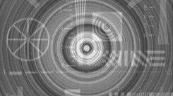
(Example of ring artifact)
I. Why Do XCT Artifacts Matter?
Before dissecting specific artifacts, let's first understand why this topic is so critical. XCT images are complex images reconstructed from thousands of X-ray attenuation measurements acquired around the sample/patient. The intricate process of converting raw data into cross-sectional images is a marvel of modern medical technology. However, this process is not always perfect.
Artifacts are discrepancies between the reconstructed XCT values in the image and the true attenuation coefficients of the scanned object. They can manifest in several ways:
Misleading Densities:Making tissues and different materials appear denser or less dense than they actually are.
Obscured Anatomy:Hiding or blurring important structures.
False Lesions:Producing patterns that could be mistaken for disease.
Reduced Image Clarity:Overall degrading the diagnostic quality of the scan.
The presence of significant artifacts may necessitate repeat scans, leading to higher radiation doses for patients and increased medical costs. Therefore, a thorough understanding of their origins and mitigation strategies is crucial.
II. Beam Hardening: 'Cupping' and 'Streak' Artifacts
Beam hardening is arguably one of the most prevalent physics-based artifacts in CT imaging. It stems from the polychromatic nature of the X-ray beam produced by the CT scanner (Figure 1 below).
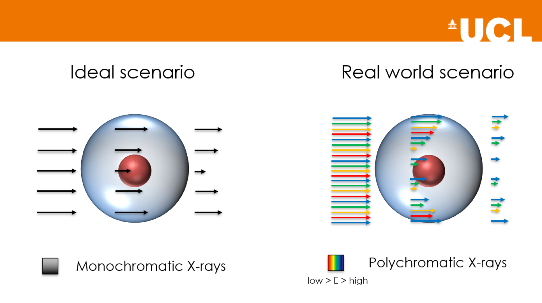
Figure 1. Example of the effect of monochromatic vs. polychromatic X-ray beams passing through an object
What causes beam hardening?
The X-ray beam emitted from the X-ray tube does not consist of photons with identical energies; instead, it is an energy spectrum. As this beam passes through an object, lower-energy (softer) X-rays are more readily attenuated (absorbed or scattered) than higher-energy (harder) X-rays. This preferential absorption of low-energy photons causes the average energy of the X-ray beam to increase as it passes through the object—hence the term 'beam hardening'.
Reconstruction algorithms in CT typically assume a monochromatic (single-energy) X-ray beam (Figure 1). When beam hardening effects violate this assumption, inconsistencies arise in the attenuation data, leading to artifacts.
How does beam hardening manifest?
Beam hardening primarily manifests in two ways:
Cupping Artifact:In images of relatively homogeneous, dense objects (such as the head or cylindrical phantoms), the center of the object appears artificially darker (lower CT number) than the periphery. This gives the object a 'cupped' or bowl-shaped appearance in its density profile. This occurs because the beam path through the center of the object is the longest, becomes 'harder', and leads to an underestimation of attenuation in the central region. (Left side of Figure 2)
Inter-Petrous Streaks:Dark streaks or bands frequently appear between two dense objects in the image (e.g., between the petrous bones of the skull or around metal implants in medical CT). These dark bands may also be accompanied by bright streaks. This is because beams passing through both dense objects simultaneously are significantly hardened, leading to an underestimation of attenuation along that path, compared to paths passing through only one object or softer tissue. (Right side of Figure 2 below).
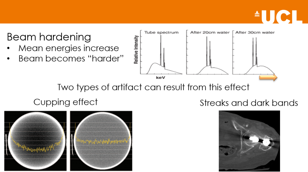
Figure 2. Illustration of beam hardening artifacts
Taming the Beam: Mitigation Strategies for Beam Hardening
Several methods can be used to minimize beam hardening artifacts:
1. Hardware Solutions
Filtration: Adding filters at the X-ray tube (e.g., thin sheets of copper, aluminum, tin, etc.) helps 'pre-harden' the beam by partially removing low-energy photons before they reach the sample. This makes the beam more effectively approach monochromaticity.
Higher kVp: Using a higher tube voltage peak (kVp) produces a higher average X-ray beam energy, which is less prone to hardening. However, this may reduce image contrast.
2. Software Corrections
Beam Hardening Correction Algorithms:Most modern CT scanners include sophisticated software algorithms that attempt to correct for beam hardening. These algorithms can linearize the attenuation data or iteratively reconstruct the image to account for the polychromatic nature of the beam.
Dual-Energy CT (DECT):This advanced technique involves acquiring data at two different X-ray energy levels. By analyzing the differences in attenuation at these energies, materials can be better differentiated, and beam hardening effects can be significantly reduced. Virtual monochromatic images can be reconstructed, effectively eliminating the polychromatic beam problem.
3. Sample Positioning and Technique
Avoid scanning very thick and dense regions whenever possible. Use an appropriate scan field of view (FOV) and reconstruction kernel.
III.Streak Artifacts
While beam hardening is a major cause of streak artifacts, they can also originate from several other sources. These artifacts appear as incorrect Hounsfield Unit (HU) values, streaks, or bands in the image, often radiating from high-contrast regions.
What causes streak artifacts? (Besides beam hardening)
1. Photon Starvation (Noise-Induced Streaks):When the X-ray beam passes through a very dense part of the sample, the number of photons reaching the detector can become extremely low. This 'photon starvation' results in very noisy projection data. During reconstruction, this high noise is amplified and back-projected into the image as prominent streaks, typically in the direction of maximum attenuation.
2. Metal Artifacts:The presence of metallic objects (e.g., dental fillings, surgical clips, prosthetic devices, spinal fixation hardware) is a well-known cause of severe streak artifacts. This is due to a combination of extreme beam hardening (metals have very high attenuation coefficients), photon starvation, scatter, and metal edge effects. The resulting streaks can be so severe that they render surrounding anatomy non-diagnostic. (Figure 3 below).
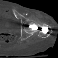
Figure 3. Metal artifacts
3. Patient Motion:If the patient/object moves during the scan (whether voluntary (not the sample itself :)) or involuntary, such as respiratory or cardiac motion), the data acquired for different projections becomes inconsistent. The reconstruction algorithm misinterprets this inconsistency, leading to streaks, blurring, or ghosting artifacts, especially around high-contrast interfaces. (Figure 4 below)
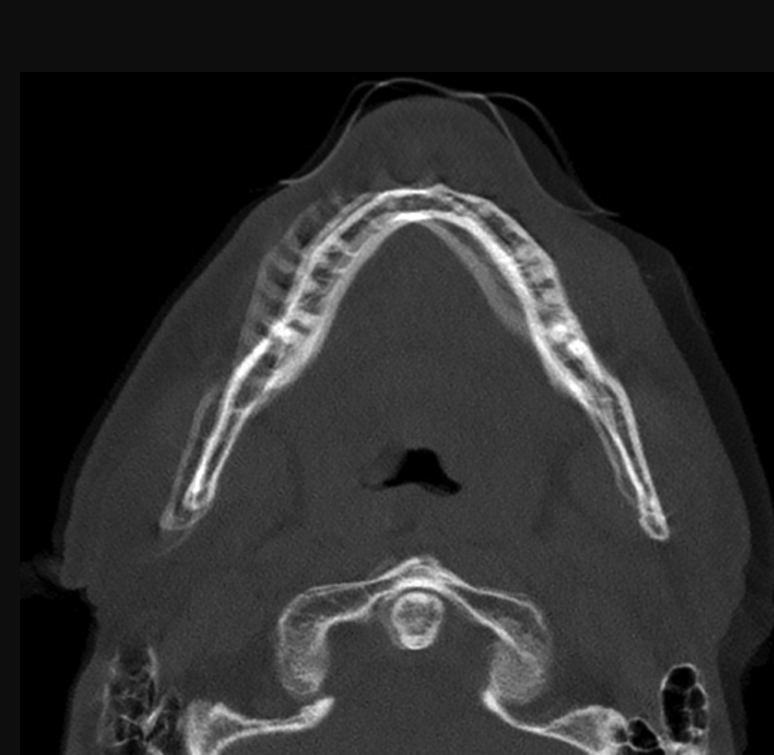
Figure 4. Sample motion artifact.
4. Partial Volume Effect:While not always streaks, when a voxel contains a mixture of materials with very different attenuation values (e.g., dense bone and soft tissue), the resulting CT number is an average. If this occurs at a sharp, obliquely oriented interface, it can sometimes lead to a streaky or band-like appearance. (Figure 5 below)
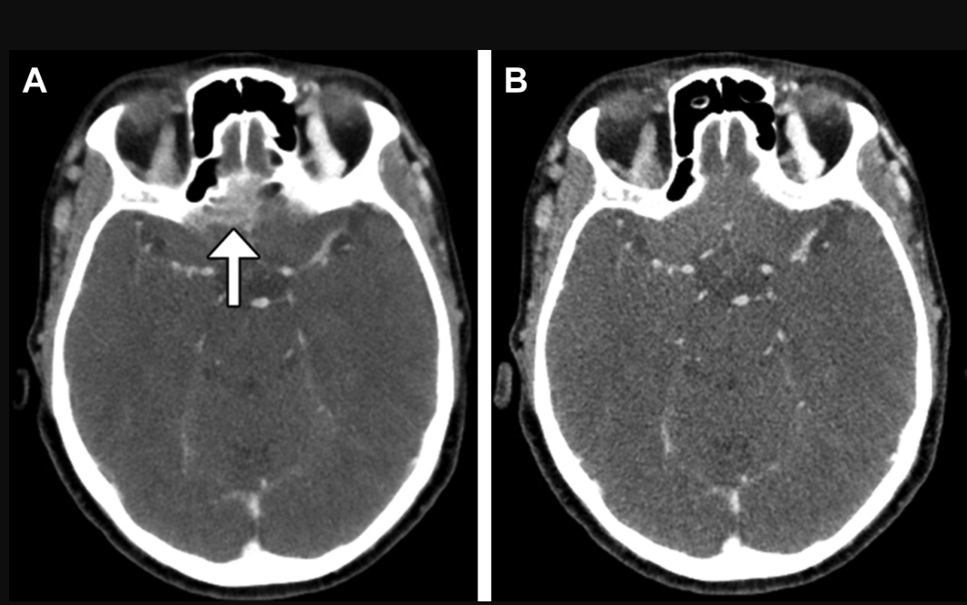
Figure 5. Partial volume effect.
Mitigation Strategies for Streak Artifacts
Dealing with streak artifacts depends largely on their cause:
1. For Photon Starvation:
(1) Increase Tube Current and/or Tube Voltage:Higher tube current (mA) increases the number of photons, while higher kVp increases photon penetration.
(2) Adaptive Filtering/Tube Current Modulation:Modern scanners can automatically adjust the tube current based on the object's attenuation at different projections, allowing more photons through denser regions.
(3) Iterative Reconstruction and Deep Learning Algorithms:These advanced reconstruction techniques handle noisy data more effectively and can significantly reduce streak artifacts compared to traditional filtered back projection (FBP).
2. For Metal Artifacts:
(1) Metal Artifact Reduction (MAR) Software:Specialized algorithms are designed to identify and correct data corrupted by metal. These algorithms may involve replacing affected projection data with interpolated values or using iterative methods.
(2) Dual-Energy CT:As with beam hardening, DECT helps differentiate metal from tissue and generates virtual monochromatic images at higher energies, reducing metal-induced streaks.
(3) Increase Tube Voltage:Improves penetration through metal.
(4) Thin-Slice Scanning:Sometimes helps to isolate the artifact.
3. For Patient Motion (Medical CT):
(1) Patient Communication and Immobilization:Clear instructions, comfortable positioning, and immobilization devices can reduce voluntary motion.
(2) Faster Scan Times:Modern multi-detector CT (MDCT) scanners offer very rapid acquisitions, minimizing the opportunity for motion.
(3) ECG Gating/Respiratory Gating:For cardiac and thoracic imaging, ECG gating synchronizes data acquisition with the cardiac cycle, while respiratory gating acquires data during specific breathing phases.
(4) Motion Correction Algorithms:Some advanced software can perform retrospective motion artifact correction.
IV.Ring Artifacts: Unwanted Circles
Ring artifacts, as the name suggests, are circular or concentric ring patterns superimposed on the CT image, typically centered on the axis of rotation. They are a classic example of scanner-based artifacts.
What causes ring artifacts?
Ring artifacts are primarily caused by detector malfunctions or calibration errors in the CT scanner:
(1) Detector Drift/Gain Variation:If one or more detector elements are miscalibrated, meaning their response to a given X-ray intensity is consistently higher or lower than their neighbors, this error is back-projected at all angles, producing a ring.
(2) Defective Detector Elements:A non-functioning or intermittently functioning detector element can also cause inconsistent readings, resulting in ring artifacts.
(3) Contamination:In rare cases, foreign material on the CT tube aperture or detector window (such as a drop of contrast agent) can cause ring patterns.
In essence, any systematic error from one or more detector elements that is not corrected by calibration procedures can lead to these artifacts.
How do ring artifacts appear?
Ring artifacts are often quite conspicuous (Figure 6 below):
(1) They appear as sharp, complete, or partial circles.
(2) They are centered on the scanner's isocenter.
(3) They can be subtle or very prominent, sometimes obscuring underlying anatomy/sample features.
(4) If multiple detector pixels are affected, multiple rings may appear.
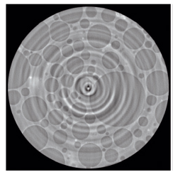
Figure 6. Example of ring artifacts
Strategies for Eliminating Ring Artifacts
Preventing and correcting ring artifacts typically involves CT scanner maintenance and calibration:
(1) Detector Calibration:Regular and thorough calibration of the detector array is the most critical preventive measure. This includes air calibration (performed with no object in the beam) and usually phantom calibration to ensure all detector elements respond accurately and uniformly.
(2) Software Correction:Many scanners have software algorithms designed to detect and correct for minor detector variations. These algorithms can identify faulty detector readings in the sinogram (raw data) and replace them with interpolated values from adjacent, properly functioning detectors. (Figure 7 below)
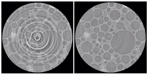
Figure 7. Software correction used to mitigate ring artifacts.
(3) Detector Replacement/Repair:If a detector element consistently fails and calibration/software correction is insufficient, a service engineer may be required for repair or replacement.
(4) Cleaning:Ensure CT components, including the X-ray tube window and detector covers, are clean and free of obstructions.
V.Aliasing (Undersampling) Artifacts:
The Moiré Pattern Impersonator
Aliasing artifacts, sometimes called undersampling artifacts, occur when fine details or sharp edges in the object are not sampled sufficiently adequately by the detector system. This insufficient sampling causes high-frequency signals to be misrepresented as lower-frequency signals in the reconstructed image, resulting in distortion (Figure 8).
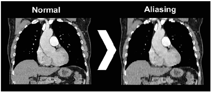
Figure 8. Example of aliasing artifact
Causes of Aliasing Artifacts
The Nyquist sampling theorem states that to accurately represent a signal, it must be sampled at a rate at least twice its highest frequency component. In CT:
(1) Insufficient Projection Sampling (Angular Undersampling):If too few projection views are acquired as the sample rotates, fine details may be missed or misinterpreted, leading to fine streaks emanating from sharp edges or dense objects. This is more common in older scanners or fast protocols ('fast protocols' in CT scanning refer to optimized workflows and imaging techniques to increase speed, not necessarily a single universal protocol).
(2) Insufficient Ray Sampling (Spatial Undersampling):If the detector pixels are too large relative to the details being imaged, or the number of samples per projection is too low, aliasing can occur. This can lead to Moiré-like patterns (wavy or zebra-stripe patterns) when imaging objects with regular high-frequency structures, such as test phantoms with closely spaced bars.
In essence, the scanner does not 'look' sufficiently or in enough detail to accurately capture the object's structure.
How do aliasing artifacts appear?
Aliasing artifacts can manifest as:
(1) Fine streaks or radial lines emanating from the edges of dense structures. These often appear at the periphery of the scanned object.
(3) Moiré patterns: Wavy or geometric patterns, particularly when imaging objects with periodic structures finer than the sampling interval.
(3) Overall loss of sharpness or a 'stair-step' pattern along oblique edges.
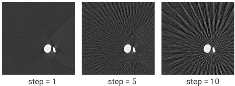
Figure 9. Illustration of aliasing artifacts in CT data. Step = 5 and step = 10 use only 10% and 20% of the original data for reconstruction, respectively. You can see the effect of streaks produced by using too few projections. Courtesy of Rigaku
Mitigation Strategies for Aliasing Artifacts
Minimizing aliasing involves ensuring adequate data sampling:
(1) Increase the Number of Projections:Acquiring more views per rotation (higher angular sampling) helps mitigate this, but it may slightly increase scan time or dose. Modern scanners typically provide sufficient projection sampling for most applications.
(2) Use a Smaller Field of View (FOV) or Magnified Reconstruction:Focusing the reconstruction on a smaller region effectively increases the sampling density in that area.
(3) Thinner Slices and Smaller Detector Pixels:Higher spatial resolution capabilities (smaller detectors, thinner reconstruction slices) inherently mean better sampling of fine details.
(4) Reconstruction Kernel (a.k.a. Filter Function):While not directly preventing aliasing, a smoother reconstruction kernel can sometimes mask the appearance of aliasing artifacts, at the cost of spatial resolution. Sharper kernels may exacerbate them.
(5) Scanner Design:Modern CT scanners are typically designed with detector configurations and acquisition protocols to minimize aliasing in typical imaging. However, it can still be an issue in high-resolution research applications or when imaging samples with fine patterns.
VI. Conclusion
While the world of CT artifacts may seem complex, understanding their origins is the first step toward mastering image quality. The deceptive patterns of beam hardening, streaks from various sources, ring artifacts, and aliasing each present unique challenges. Fortunately, advances in CT technology—from sophisticated hardware design and intelligent acquisition protocols to powerful iterative reconstruction algorithms—are continually providing us with better tools to combat these unwanted image intruders.
By remaining vigilant, performing regular quality control and calibration, selecting appropriate scan parameters, and leveraging the latest technological advancements, we can significantly reduce the impact of artifacts. This ensures that the images we obtain are not just pictures, but accurate, reliable representations of patient anatomy, paving the way for accurate diagnosis and effective treatment.
Stay tuned for future issues where we will explore new and interesting topics!




About Dr. Francesco Iacoviello
Francesco Iacoviello is the Experimental Manager of the EIL X-ray Facility in the Department of Chemical Engineering at University College London (UCL). He obtained his PhD in Mineralogy and Earth Sciences from the University of Siena, Italy, in 2012, before moving to the University of São Paulo, Brazil, where he served as an X-ray diffraction specialist and laboratory manager at the Oceanographic Institute. Francesco joined the EIL in 2015, and his research spans a wide range of multi-scale X-ray computed tomography characterization, from electrochemical devices to shale gas rocks, carbon capture and storage systems, and geological materials such as micrometeorites.
TOP-UNISTAR
About Top Unistar
Top Unistarhas translated thisXCT Mastery Monthlyseries into Chinese and disseminated it with the authorization of Dr. Francesco Iacoviello, aiming to share X-ray CT tips, potential tricks, and insights with a wider audience and to build a professional exchange community.
The interaction between scientific research and industry is a vital driver for industrial development.Top Unistaras asupplier of EUV-X-ray core components and solutionsadheres to the core philosophy ofTechnology Without Borders, Industry Symbiosisand is committed to building an open and inclusive exchange platform, not only hoping to introduce outstanding achievements into China but also dedicated to bringing Chinese scientific research results to the world.

·END·
Previous Issues:
[Issue 2] Unveiling the Invisible: The Miracle of X-ray Generation in Computed Tomography
Content: Francesco Iacoviello
Proofreading: Kevin
Editor: Sylvia

Disclaimer:
Part of the content (including images) in this article is sourced from the internet. The copyright and views of the quoted parts belong to the original authors. Beijing Top Unistar Technology Co., Ltd. publishes and reposts this information for the purpose of conveying more industry news and online sharing. If you believe this article contains infringing content, please contact us, and we will address it promptly. If you have any questions, please feel free to contact us at any time.
FROM READING TO APPLICATION
Put this knowledge to work
Need to assess product suitability, discuss experimental conditions or find technical support? Explore our products and services, or discuss this resource with us.